- 您现在的位置:买卖IC网 > Sheet目录975 > DK1A1B-12V (Panasonic Electric Works)RELAY GEN PURPOSE DPST 8A 12V
�� ��
��
��DK�
�2.� Speci?cations�
�Characteristics�
�Arrangement�
�Item�
�1� Form� A�
�Speci?cations�
�1� Form� A� 1� Form� B� 2� Form� A�
�Contact�
�Rating�
�Contact� resistance� (Initial)�
�Contact� material�
�Nominal� switching� capacity� (resistive� load)�
�Max.� switching� power� (resistive� load)�
�Max.� switching� voltage�
�Max.� switching� current�
�Nominal� operating� power�
�Min.� switching� capacity� (Reference� value)*� 1�
�Insulation� resistance� (Initial)�
�Max.� 30� m� ?� (By� voltage� drop� 6� V� DC� 1A)�
�Au-?ashed� AgSnO� 2� type� Au-?ashed� AgNi� type�
�10� A� 250� V� AC,� 10� A� 30� V� DC� 8� A� 250� V� AC,8� A� 30� V� DC� 8� A� 250� V� AC,8� A� 30� V� DC�
�2,500VA,� 300� W� 2,000� VA,� 240� W� 2,000� VA,� 240� W�
�250� V� AC,� 125� V� DC� 250� V� AC,� 125� V� DC� 250� V� AC,� 125� V� DC�
�10� A� 8� A� 8� A�
�200� mW�
�10m� A� 5� V� DC�
�Min.� 1,000M� ?� (at� 500V� DC)� Measurement� at� same� location� as� “Breakdown� voltage”� section.�
�Breakdown� voltage�
�(Initial)�
�Between� open� contacts�
�Between� contact� and� coil�
�1,000� Vrms� for� 1min.� (Detection� current:� 10mA.)�
�4,000� Vrms� for� 1min.� (Detection� current:� 10mA.)�
�Electrical�
�Surge� breakdown�
�voltage*� 2� (Initial)�
�between� contacts� and� coil�
�10,000� V�
�characteristics�
�Temperature� rise� (coil)� (at� 65� °� C� 149� °� F� )�
�Operate� time� [Set� time]� (at� 20� °� C� 68� °� F� )�
�Release� time� [Reset� time]� (at� 20� °� C� 68� °� F� )�
�Max.� 40� °� C� (By� resistive� method,� nominal� voltage� applied� to� the� coil;� max.� switching� current)�
�Max.� 10� ms� (Approx.� 5� ms)� [10� ms� (Approx.� 5� ms)]�
�(Nominal� coil� voltage� applied� to� the� coil,� excluding� contact� bounce� time.)�
�Max.� 8� ms� (Approx.� 3� ms)� [10� ms� (Approx.� 3� ms)]�
�(Nominal� coil� voltage� applied� to� the� coil,� excluding� contact� bounce� time.)� (without� diode)�
�Mechanical�
�characteristics�
�Shock� resistance�
�Vibration� resistance�
�Functional�
�Destructive�
�Functional�
�Destructive�
�Min.� 98� m/s� 2� (Half-wave� pulse� of� sine� wave:� 11� ms;� detection� time:� 10� μ� s.)�
�Min.� 980� m/s� 2� (Half-wave� pulse� of� sine� wave:� 6� ms.)�
�10� to� 55� Hz� at� double� amplitude� of� 1.5� mm� (Detection� time:� 10� μ� s.)�
�10� to� 55� Hz� at� double� amplitude� of� 3� mm�
�Expected� life�
�Conditions�
�Mechanical�
�Electrical�
�Conditions� for� operation,� transport� and� storage*� 3�
�Max.� operating� speed� (at� rated� load)�
�Min.� 5� � 10� 7� (at� 300� times/min.)�
�Min.� 10� 5� (resistive� load,� at� 20� times/min.,� at� rated� capacity)�
�Ambient� temperature:� –40� °� C� to� +65� °� C� –40� °� F� to� +149� °� F� ,�
�Humidity:� 5� to� 85%� R.H.� (Not� freezing� and� condensing� at� low� temperature)�
�20� times/min.�
�Unit� weight�
�Approx.� 5� g� .18� oz�
�Approx.� 6� g� .21� oz�
�Approx.� 6� g� .21� oz�
�Notes:� *1.� This� value� can� change� due� to� the� switching� frequency,� environmental� conditions,� and� desired� reliability� level,� therefore� it� is� recommended� to� check� this� with� the�
�actual� load.�
�*2.� Wave� is� standard� shock� voltage� of� ±� 1.2� ×� 50� μ� s� according� to� JEC-212-1981�
�*3.� The� upper� limit� of� the� ambient� temperature� is� the� maximum� temperature� that� can� satisfy� the� coil� temperature� rise� value.� Refer� to� Usage,� transport� and� storage�
�conditions� in� NOTES.�
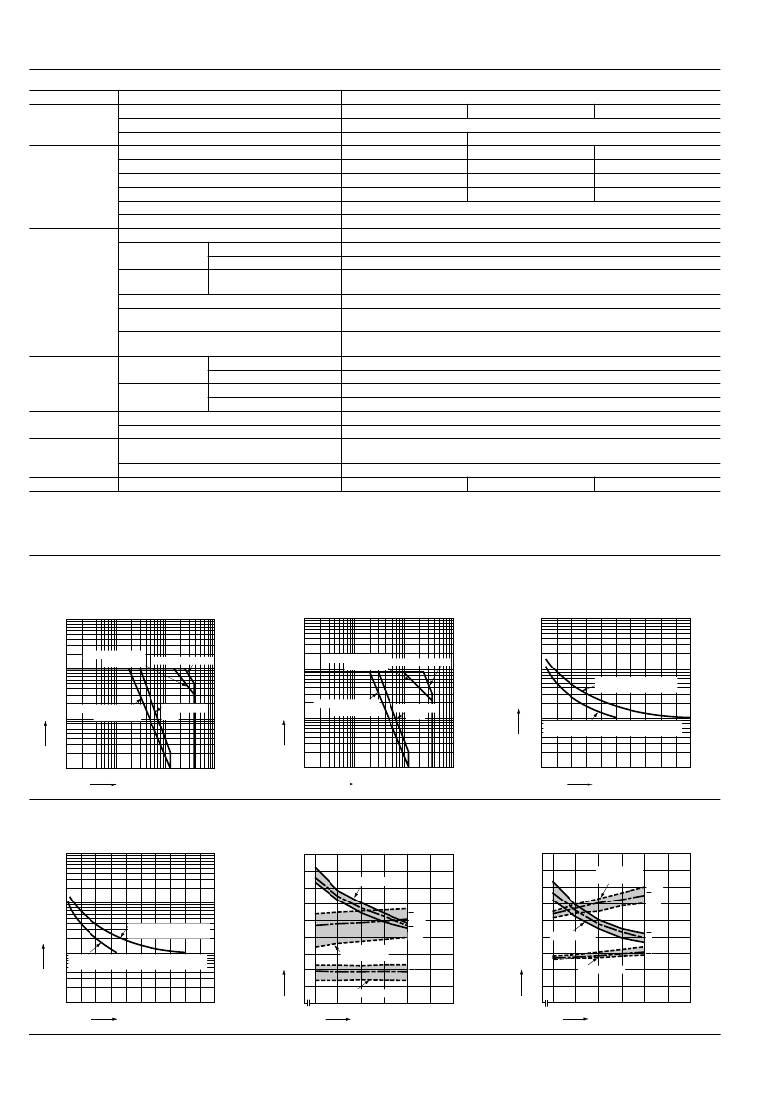
�REFERENCE� DATA�
�1-(1).� Maximum� operating� power� (1� Form� A)�
�100�
�1-(2).� Maximum� operating� power�
�(1� Form� A� 1� Form� B,� 2� Form� A)�
�2-(1).� Life� curve� (1� Form� A)�
�1,000�
�10�
�AC� inductive� load�
�(cos� ?� =� 0.4)�
�AC resistive load�
�10�
�AC� inductive� load�
�(cos� ?� =� 0.4)� AC resistive load�
�100�
�5�
�250� V� AC� resistive� load�
�30� V� DC� resistive� load�
�1�
�DC� inductive� load�
�(L/R� =� 7� ms)�
�DC� resistive�
�load�
�1�
�DC� inductive� load�
�(L/R� =� 7� ms)�
�DC� resistive�
�load�
�10�
�250� V� AC� inductive� load� (cos� ?� =� 0.4)�
�30� V� DC� inductive� load� (L/R� =� 7� ms)�
�0.1�
�10�
�100�
�1,000�
�0.1�
�10�
�100�
�1,000�
�1�
�0�
�1�
�2�
�3�
�4�
�5�
�6�
�7�
�8�
�9�
�10�
�Contact� voltage,� V�
�2-(2).� Life� curve�
�(1� Form� A� 1� Form� B,� 2� Form� A)�
�1,000�
�Contact� voltage,� V�
�3-(1).� Operate/Release� time� (1� Form� A)�
�Tested� sample:� DK1a-24V,� 5� pcs.�
�9�
�Contact� current,� A�
�3-(2).� Operate/Release� time�
�(1� Form� A� 1� Form� B,� 2� Form� A)�
�Tested� sample:� DK1a1b-12V,� 5� pcs.�
�9�
�8�
�8�
�Release� time�
�7�
�Operate� time�
�7�
�(with� diode)�
�Max.�
�x�
�100�
�6�
�Max.�
�6�
�Min.�
�10�
�250� V� AC� resistive� load�
�30� V� DC� resistive� load�
�250� V� AC� inductive� load� (cos� ?� =� 0.4)�
�30� V� DC� inductive� load� (L/R� =� 7� ms)�
�5�
�4�
�3�
�2�
�Release� time�
�(with� diode)�
�x�
�Max.�
�x�
�Min.�
�Min.�
�Max.�
�x�
�5�
�4�
�3�
�2�
�Operate� time�
�Release� time�
�Max.�
�x�
�Min.�
�Max.�
�x�
�Min.�
�1�
�Release time�
�Min.�
�1�
�1�
�0�
�1�
�2�
�3�
�4�
�5�
�6�
�7�
�8�
�9�
�10�
�0�
�80�
�90�
�10�
�110�
�120�
�130�
�140�
�0�
�80�
�90�
�10�
�110�
�120�
�130�
�140�
�Contact� current,� A�
�Coil� applied� voltage,%V�
�Coil� applied� voltage,%V�
�Panasonic� Corporation�
�Automation� Controls� Business� Unit�
�industrial.panasonic.com/ac/e/�
�ASCTB177E� 201202-T�
�发布紧急采购,3分钟左右您将得到回复。
相关PDF资料
DK20S16
SHIELD DRIP KIT 20"
DK24S16
SHIELD DRIP KIT 24"
DK30S16
SHIELD DRIP KIT 30"
DK36S16
SHIELD DRIP KIT 36"
DK86065-2
KIT EVAL 16BIT DAC FOR MB86065
DLP-TILT-G
BOARD EVAL ACCEL/TILT/VIB SENSOR
DM160211
KIT DEV MTOUCH PROJ CAPACITIVE
DM163026
BOARD DEMO LOW POWER SOLUTIONS
相关代理商/技术参数
DK1A1B-12V
制造商:Panasonic Electric Works 功能描述:Power Relay
DK1A1B12VF
制造商:Panasonic Electric Works 功能描述:Electromechanical Relay SPST-NO/SPST-NC 8A 12VDC 720Ohm Through Hole
DK1A1B24J
制造商:Panasonic Electric Works 功能描述:
DK1-A1B24V
制造商:Panasonic 功能描述:Bulk
DK1A1B-24V
功能描述:通用继电器 8A 24VDC DPST-NO/NC
RoHS:否 制造商:Omron Electronics 触点形式:1 Form A (SPST-NO) 触点电流额定值:150 A 线圈电压:24 VDC 线圈电阻:144 Ohms 线圈电流:167 mA 切换电压:400 V 安装风格:Chassis 触点材料:
DK1A1B-24V-F
制造商:PANASONIC 功能描述:DK Series 8 A SPDT 24 VDC Through Hole Miniature Single Side Stable Power Relay 制造商:Panasonic 功能描述:DK Series 8 A SPDT 24 VDC Through Hole Miniature Single Side Stable Power Relay
DK1A1B3J
制造商:Panasonic Electric Works 功能描述:
DK1a1b-3V
功能描述:通用继电器 1FormA, 1FormB,3VDC 10A 250VAC 10A 30VDC
RoHS:否 制造商:Omron Electronics 触点形式:1 Form A (SPST-NO) 触点电流额定值:150 A 线圈电压:24 VDC 线圈电阻:144 Ohms 线圈电流:167 mA 切换电压:400 V 安装风格:Chassis 触点材料: